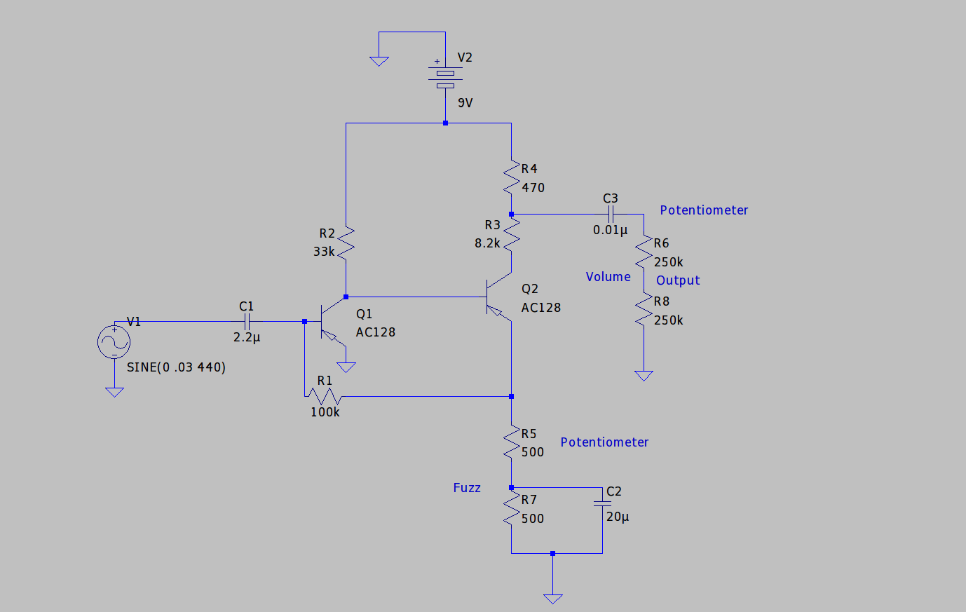

As a reminder of the theoretical description of the Fuzz I put the schematic above. I built my Fuzz a long time ago and used a schematic which was a bit different: The original Fuzz Face used to have a positive Ground. This is great if you don't plan on using multiple effects (which typically will not use positive ground). So there is the possibility to transform the circuit to a negative ground version, which is the one I used.
The old school version in combination with the negative ground combination leads to minor changes. For examples are the originally used transistors of NPN type, and the ones of the schematic I used are AC122 PNP. The data sheet can be found on the net, e.g. here.
I tried to sketch the schematic in the following image:

Now I am a bit skeptical about this diagram. The original schematic I used back then was not to be found and now everything is wired up in a messy way which makes it hard to reroute everything. But I think the schematic above gets the gist of it.
And as you can see, the inversion from positive to negative ground is obvious in the diagram, as it was in the layout on my circuit. But it is also obvious, that everything still reminds of the Schmitt Trigger.
This in mind, let's get to it. For the measurement I only compared input to output.

I used my signal generator to create a 200Hz sine with a few mV of amplitude which is what a guitar would yield. Above is the raw signal directly fed back to the scope.

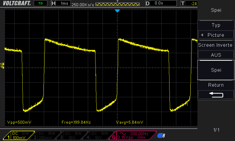
With the pots on half power, the signal already looks like the one from the simulations of the post. You have a very similar, asymmetric behaviour. Although, as mentioned above, the schematic is not exactly the same.

With both pots cranked up, the signal is still asymmetric but much more rectangular!

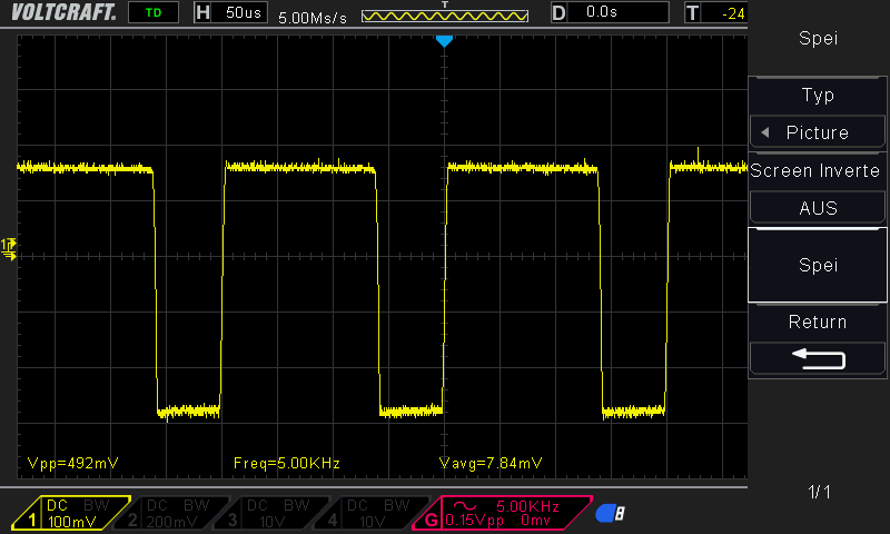
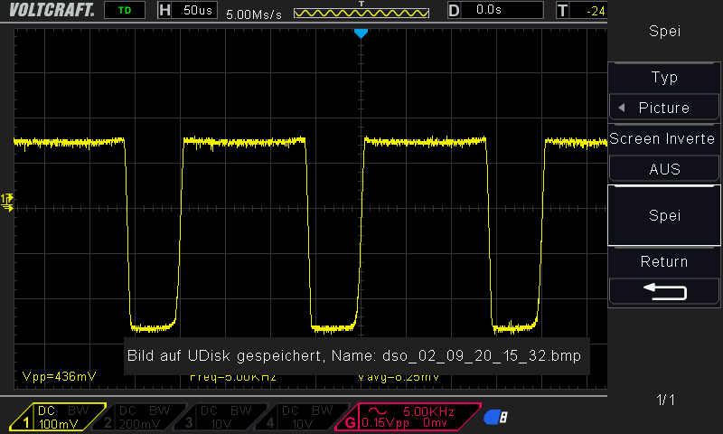
For a 5kHz sine, the behaviour looks different. Much rounder on the edges.

With the pots fully cranked, the circuit yields rectangular output, again.
In conclusion one might see, that the simulations of the last post resemble the actual device, which was built 20years ago, although the schematics do not match 100%.
Additionally, the germanium transistors are not really well known for their reproducable characteristics. All in all, the simulations might be helpful to really get a feeling of the schematic.