One of the first and most important guitar effects for Rock history is undoubtedly the Fuzz. Before effect pedals were available, musicians had limited means to create distortion. They usually ended up mistreating their equipment, which, at the time, was built to give a good clean sound.
First the speakers were intentionally damaged. By cuts in the speaker cone, the speaker would sound distorted.
Another method was to drive the amp to its limits, so it would create distortion. This is one of the reasons why musicians like Jimi Hendrix are said to have had almost deafening levels of sound volume.
But what is distortion in the first place? Well if you have a nice sine shaped input signal, an amplified clean signal would look just like that, only at a higher level. A distorted signal would be a deformed sine wave. Typically more rectangular, since the peaks of the sine are out of the limits of the amplifier to amplify them accurately. So, for a simple distorting effect pedal, you would take the signal of the guitar, amplify it to distortion (make it more rectangular) and then reduce its levels to roughly the level of the guitar.

Luckily, the easiest way to start, if you want to transform the shape of a signal, there is typically lots of material, which clever people have already created. If you want to make a sine shape square, you can go and look for example at a Schmitt Trigger. The schematic of one possible realisation of a non-inverting Schmitt Trigger (non-inverting means, that if the input is high, the output is high) is shown above and is fairly simple. The Schmitt Trigger is for example used, if you want to have a clean digital signal of a certain level. It consists, in this case, of two transistors and a few resistors, a voltage source, an input, and and output.
If you send your signal into the first transistor, it will get amplified enough, so you can trigger the second transistor properly. And the second transistor switches on and off according to its specs, which leaves the voltage on the output at the level defined by the voltage source and the resistors. You receive a wonderfully squared wave. With RI it is possible to set a limit input voltage, above which the output is pulled high and with RE a lower limit is defined, below which the Output signal is pulled low. Those limits lead to an effect which is called 'hysteresis' - it means, that, in contrast to a comparator, you have some middle ground in which the changes of the input signal have no influence on the output signal. This can be helpful if you have a noisy input signal.
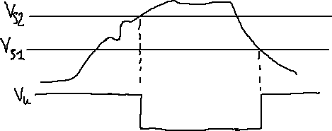
The above image demonstrates, how an inverting Schmitt Trigger (not like above, here a high input leads to a low output) might work on a signal. The signal voltage starts below the threshold and the output is high. then it rises above the threshold and the output is pulled low. After a while the signal goes down again below the threshold and the output is again high.
This does look like a good start for a distortion pedal, doesn't it? All this hysteresis stuff might not be interesting for us and we also do not want a 'perfect' rectangular output signal, it would probably sound too clean. But this will sort itself out anyway: The Germanium transistors at the time were by no means perfect. No part is, but compared to silicon they are just in another league. And so, your typical Fuzz schematic looks quite like the Schmitt Trigger schematic above. I drew one in LTSpice:
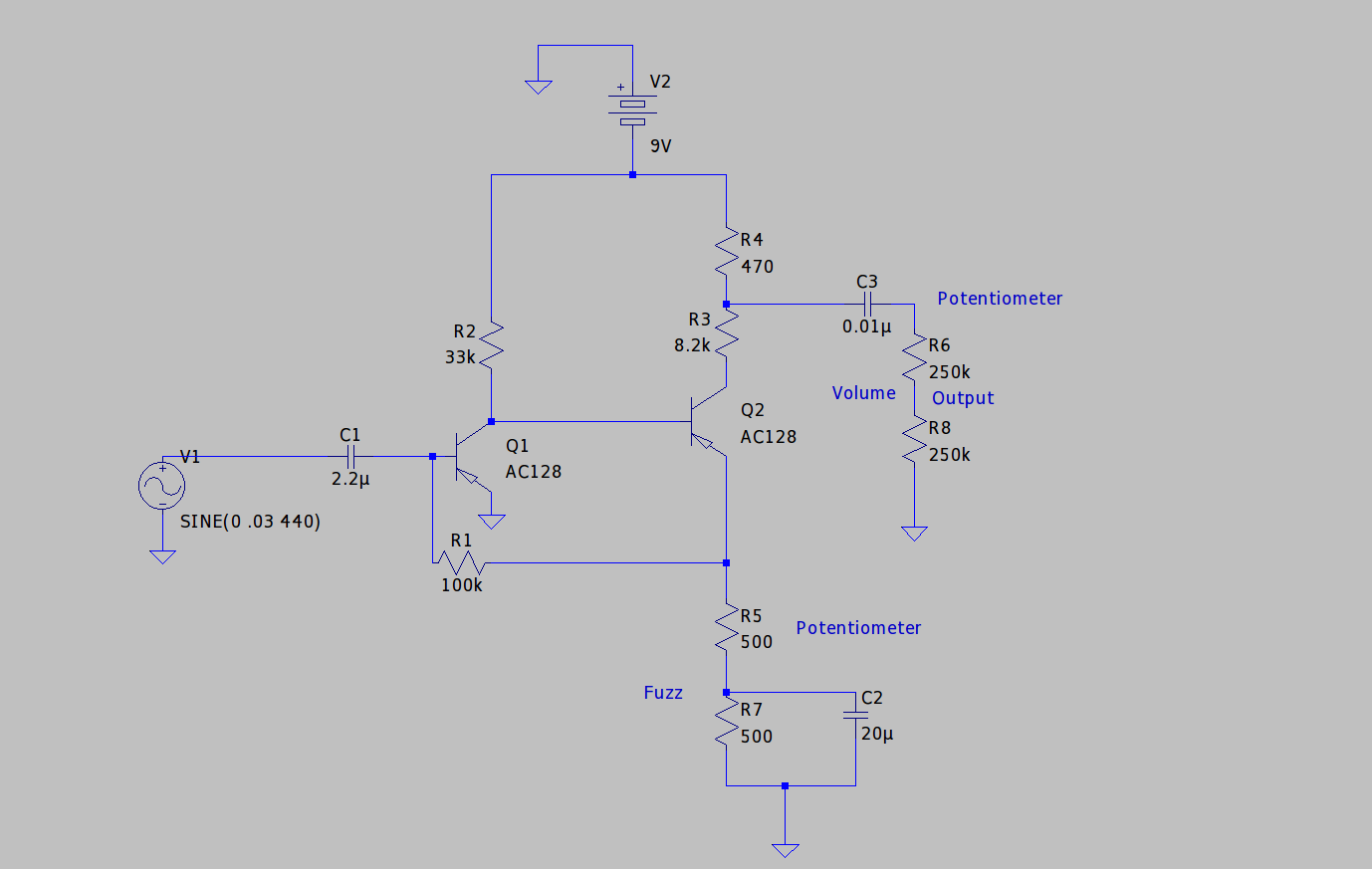
Of course there are differences. One of the most important perhaps being, that the transistors do not share an emitter resistor, but the first one is connected without an emitter resistor to GND. The emitter resistor would limit the current from the input through the base but is not needed here, since the current generated by the pickup is really small and we want maximum gain. The emitter resistor would decrease the base - emitter voltage and decrease the gain. Also notably the circuit uses a positive ground, which makes it a bit weird but is standard for these classic fuzz circuits. Also, I did not find the symbols for potentiometers, so 'Fuzz' and 'Output' potentiometers are drawn as fixed resistors.
I used models for AC128 Germanium transistors, which are very popular for this effect. Comparisons with reference data suggest, that the models are not too bad. In the next article I will have a look at my built of a fuzz effect and measure it with my scope to compare it.
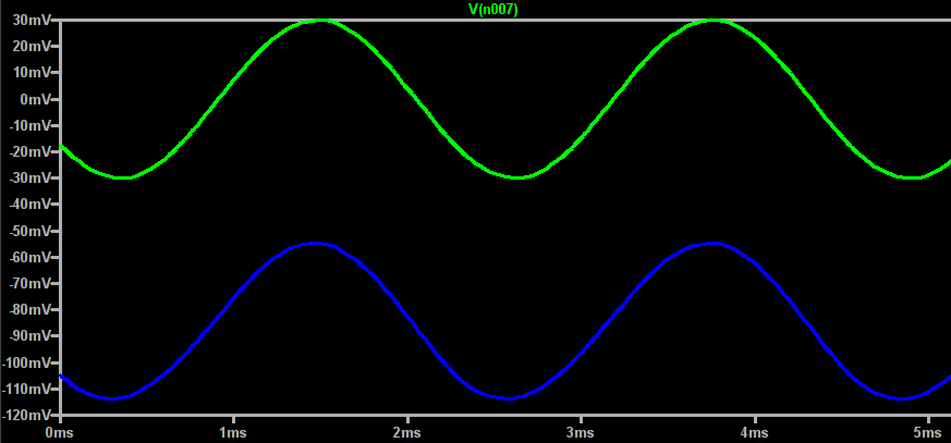
Lets have a look at the input: We start with a small sine input signal of 440Hz (note a) and have a capacitor to decouple the DC voltage of the effect. After C1 the signal voltage dropped a bit which is probably due to imperfections in the germanium transistor and parasitic capacitance.
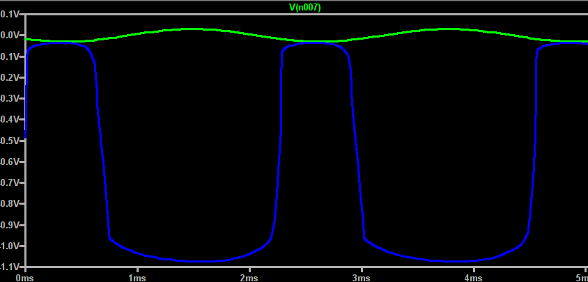
Now comes the first stage of our ampification circuit, the transistor Q1. When the input signal is low enough, the transistor Q1 is turned on and a higher current flows from emitter to collector, resulting in an amplification, inverting and distortion of the signal.
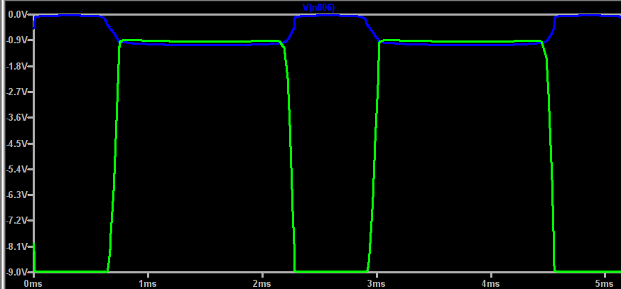
After Q1 the signal enters the second stage of the amplification circuit as it arrives at Q2. Same as before, the signal gets amplified and inverted again by Q2.
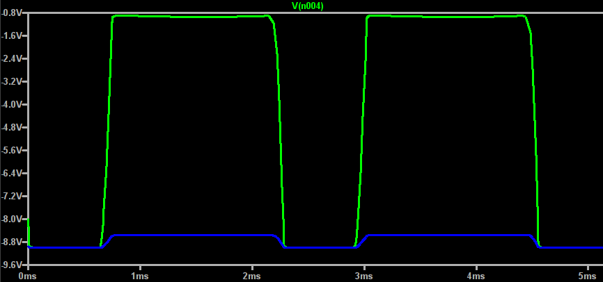
AFter Q2 we are basically done with amplification. The resistors R3 and R4 work as a voltage divider and lead to a decrease of the signal amplitude to a more appropriate level for guitar audio circuits. You would not want to enter your amp, or another effect with a 9V amplitude.
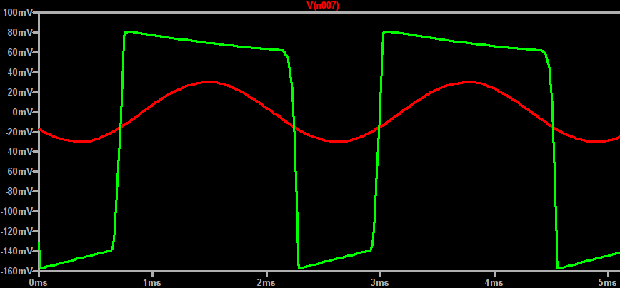
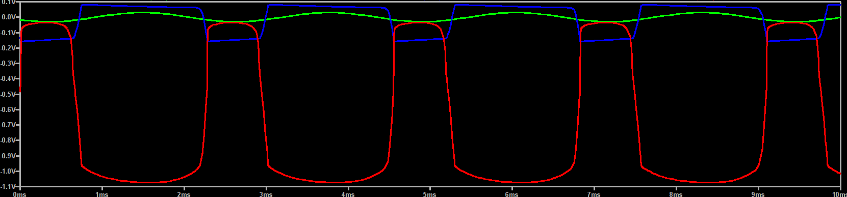
Also we need to get rid of the 9V DC which we needed for our amplification. The capacitor C3 again decouples the AC from the DC part, which leaves the Output signal roughly centered around 0V, amplified to around 240mV peak to peak and distorted.
Mission accomplished!
If you want to play with the model, you can download it here. The next article will be about a fuzz I built quite some time ago and we can see, how helpful the approach in this article really was.