If you are only slightly interested in the history of electronic design, or the silicon valley, there are three people, you will learn about really fast, absolute legends. There is Bob Widlar, whose middle finger is probably the most famous in electronics, if not the history of marketing. Then there is Jim Williams, who had the electronics of a Minuteman ballistic missile as living room decoration. The third would be legendary Bob Pease who drove a 1970 VW Stegosaurus Beetle.
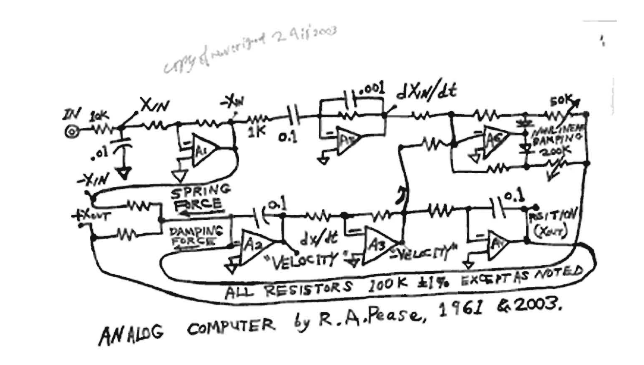
The literature from and about these three is fascinating. One of the easiest accessible is the Electronic Design Magazine column from Bob Pease, called "Pease Porridge". Some time ago, I read an article titled "What's All This Analog Computing Stuff, Anyhow?" and it is a series of three parts. In part 2 there is a description of an analog computer, which is meant to simulate a car. Well, that is really intriguing, isn't it? And the article gives a fairly simple circuit as well:
The description in the article of how the circuit works is a bit sparse, so in the last week I took a closer look at how this circuit works and how it simulates a car. In the following I want to share my notes, perhaps they are helpful to others.
The first thing is to look at the system, which shall be simulated. It is a car - not a whole car, but one wheel with suspension.
The wheel is simplified by having no rubber tire, so the street interacts directly with the suspension. If you have a look
at the forces, which are at work, you have:
--> gravity, pulling the car down,
--> a spring force as one part of the suspension
--> a damping force as another part from the suspension
--> and an effective force on the car.
The sum of all forces adds to 0, which means, that the system can be described as follows:
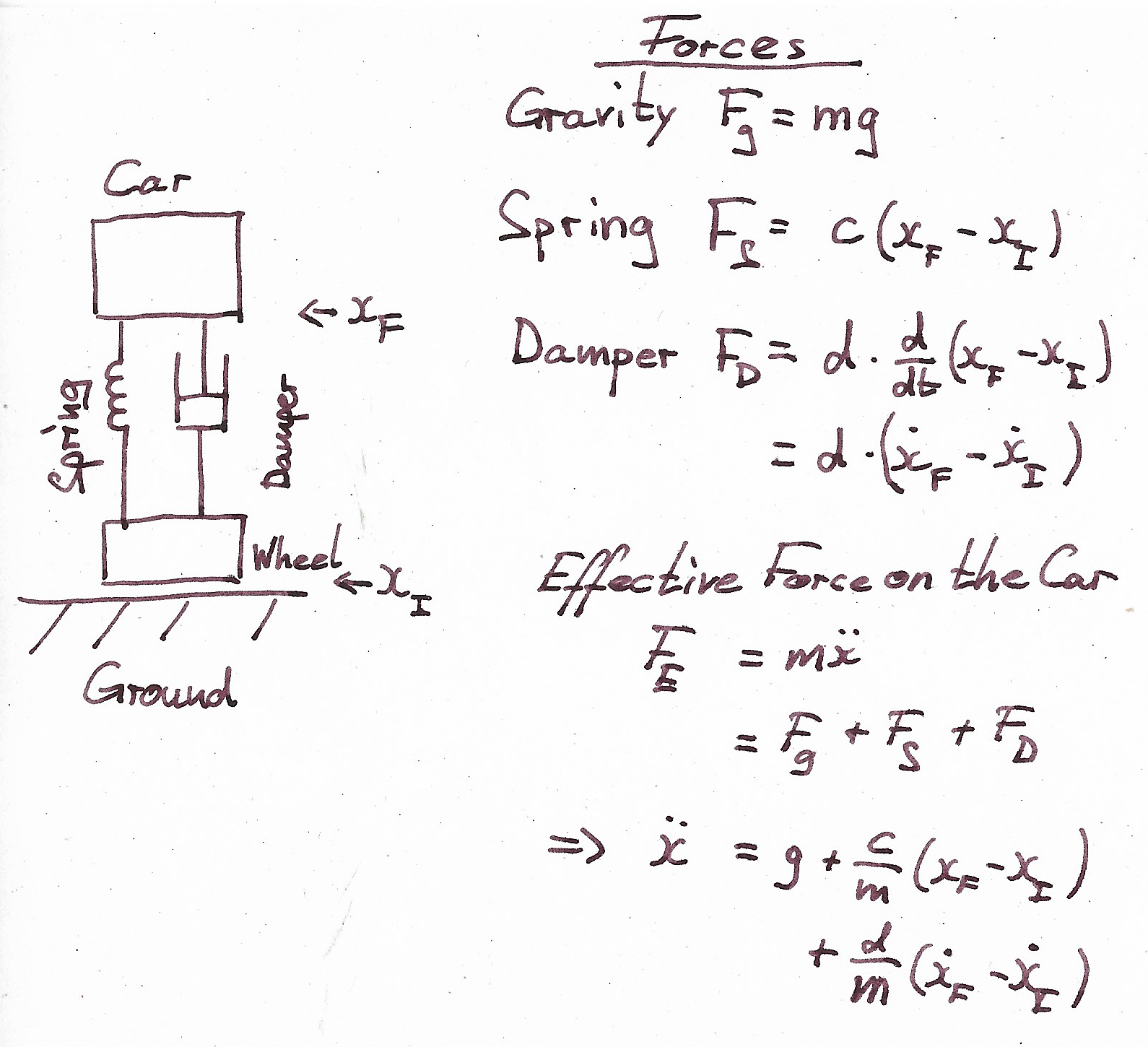
The mathematical description is fairly simple: you have a constant expression, one depending on positions, one depending on the velocities and one depending on acceleration. In the end, we arrive at a differential equation. So now we need some way of solving this.
There are circuits, based on operational amplifiers, which can invert, integrate and differentiate. The notes show how they are set up and what they do to the input signal:
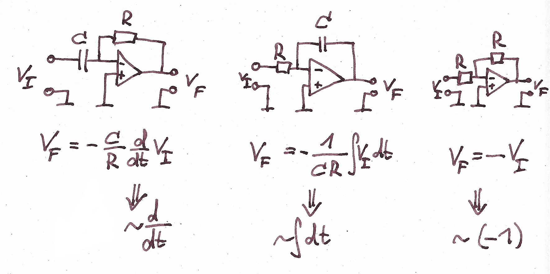
Additionally, you can think of connecting two wires as adding their signals and when you need to multiply with a factor you use a resistor.
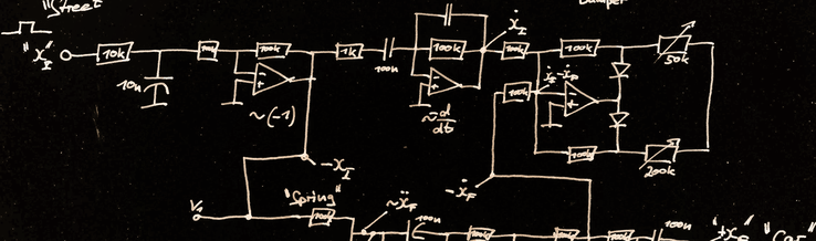
With these mathematical operations we take another look at Bob Pease's analog computer in a slightly larger drawing:
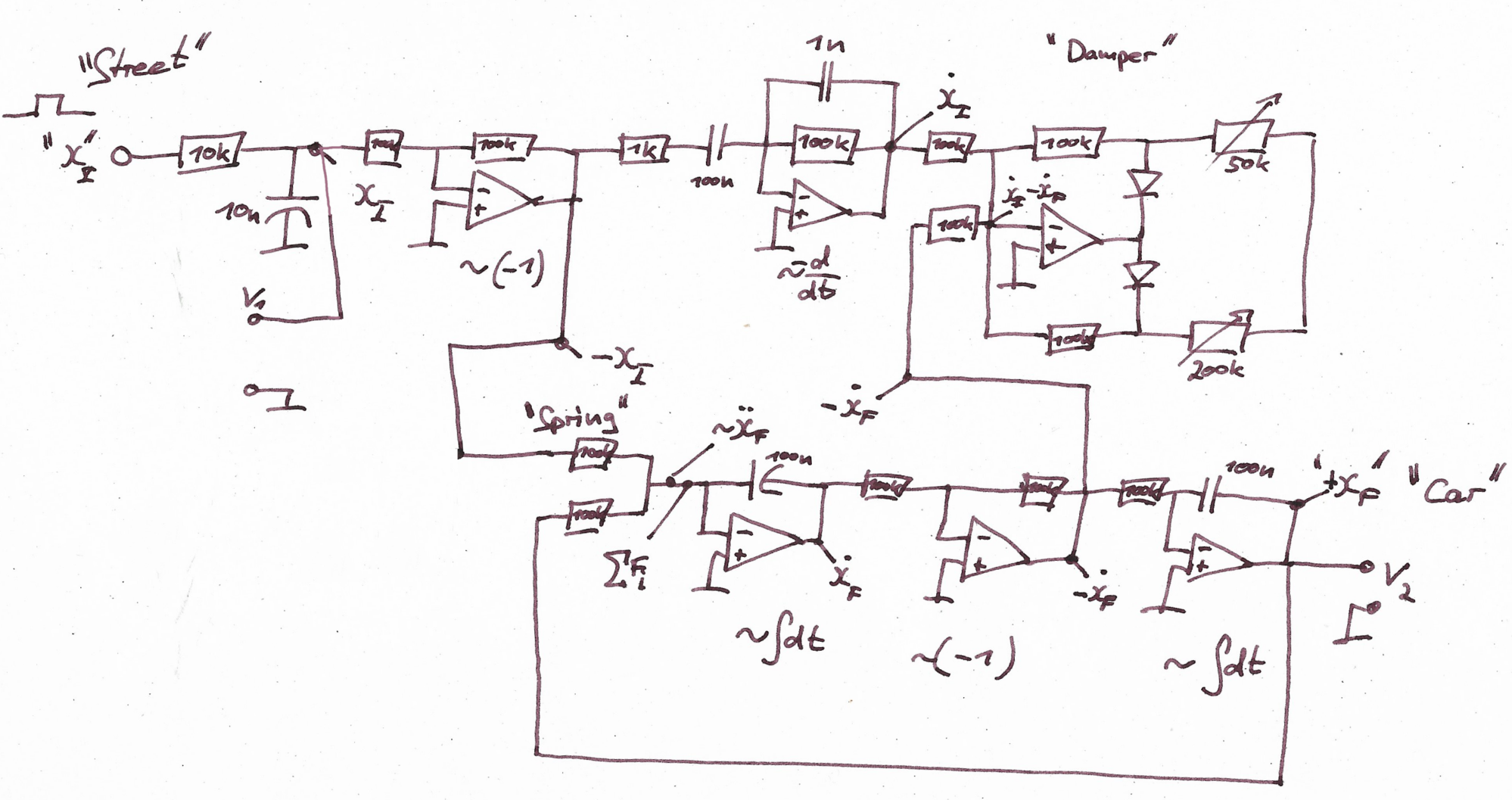
It is helpful to start looking at the lower part of the circuit, right after the part labelled "springs". Assume you already have the acceleration of the car which enters at this point with a negative sign. You will integrate it to take a look at the velocity, which is exactly what happens here: Start with the cars "-acceleration" and integrate it to get "velocity", invert it, to get the "-velocity". Then you take part of it and route it to the damper to calculate the damping force. A final integration yields the "+position" of the car which is fed back into the spring to calculate the spring force. The resistor represents the spring coefficient.
In the upper part you start on the left with the "street", which is represented as your input signal, which should be around 100Hz for this circuit. You invert it and feed some of the "-position" into the spring. Afterward you differentiate it and feed the "+velocity" into the damper, where it is mixed with the "-velocity" of the car. The damper is designed as an Op-Amp which has two feedback loops, to realize two different damping coefficients for upward and downward movement, that is why there are the diodes. The potentiometers are used to adjust your dampers. The diodes channel the current through the upper or lower potentiometer, depending on the sign of the current. Because the Op-Amp is implemented as inverting, the minus signs at the input are the other way round as in the equation above - the damper automatically adds another "-" to fix this.
You can check how it runs by looking at V_1 and V_2 on an oscilloscope. V_1 will show you the input signal, the "street". V_2 will show you the output signal, the "car". If you want to see it in action, there is an episode of the "Bob Pease Show" available on Youtube, where Pease himself explains and demonstrates his circuit.
One of, if not the most famous of Pease's quotes is: "my favorite programming language is solder". The way that the circuit above utilizes Op-Amps to solve the differential equation of a damped system is, for me, remarkable. It really is close to programming a digital computer in the way, that you break down your problem into simple tasks which you solve in specialized routines, before you bring everything back together to get the end result.
If you are interested in more of Bob Pease, which you should, you can find a lot of his columns by searching for "Bob Pease Lab notes" in your search engine of choice. You can also find more episodes of the Bob Pease Show on the web and have a look at his books for a more analog experience.
